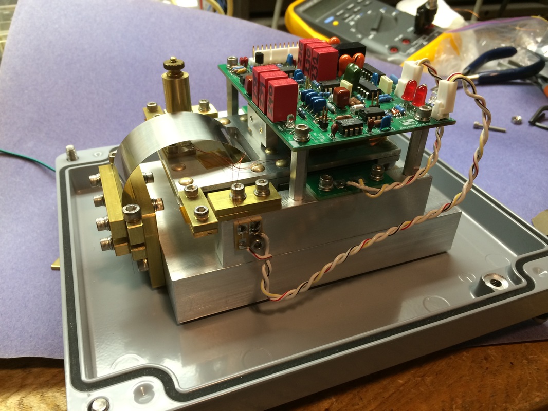
Above is a picture of my first Yuma force-balance vertical (FBV) seismometer with the case open. A case is required to shield the instrument from air currents and variations of barometric pressure which otherwise would be a huge source of noise. Visible above are the base, leaf spring with clamps, tilting boom and electronics. In this view it is hard to see the capacitance sensor and the voice coil actuator which complete the force-balance scheme.
Working on available evenings and weekends, it took me about a year to get my first Yuma up and running. |
The Yuma FBV seismometer project is a combination of mechanical fabrication, electronic fabrication or assembly, learning of a software application, site preparation to locate the sensor, and plenty of time spent thinking about the measurement and detection of the minute motion of the earth associated with the earthquakes that frequently set seismic waves traveling great distances around the globe.
This seismometer, that can be built by accomplished amateurs, achieves results that closely approach those achieved by professional instruments. This is especially true if you consider that the noise floor will almost surely be dominated by the actual site noise at any location that an amateur is likely to be able to locate the instrument. Teleseismic events can be readily captured from earthquakes occurring all around the world. My own Yuma has captured nice signals from Papua New Guinea, Japan, Nepal, Chile, Russia, and even volcanic eruptions in Iceland, all from a suburban location in California. This site describes in detail how I built my second unit. I hope this can serve as a guide for others who want to reproduce this excellent design. Note: This site is still under construction as of 11/21/15 |
Mechanical
|

ElectronicElectronic assembly with soldering of through-hole components into a circuit board and some cable fabrication, and electronic measurements are required.
|

ComputerThe ADC (analog to digital) circuit, and the interface to a computer with specialized logging software can be purchased from a friendly source for a modest amount (<$250). Then the computer task becomes one of learning the application, adjusting settings, tuning the filters and enjoying the results.
|
Mechanical
First of all, here are the mechanical plans:
To download, right-click on the button below, select "Save link as.." then navigate to where you want to save the plans, and then select SAVE.
Next you will need a viewer. Click here to go to the website to download Brava Free DWG viewer:
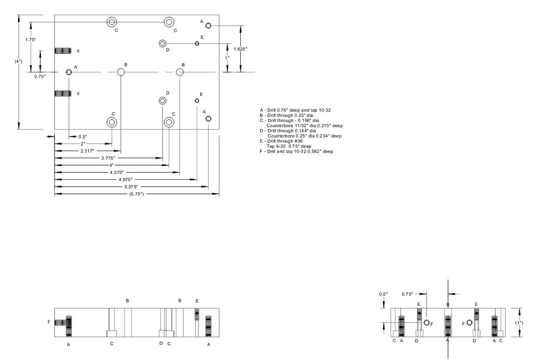
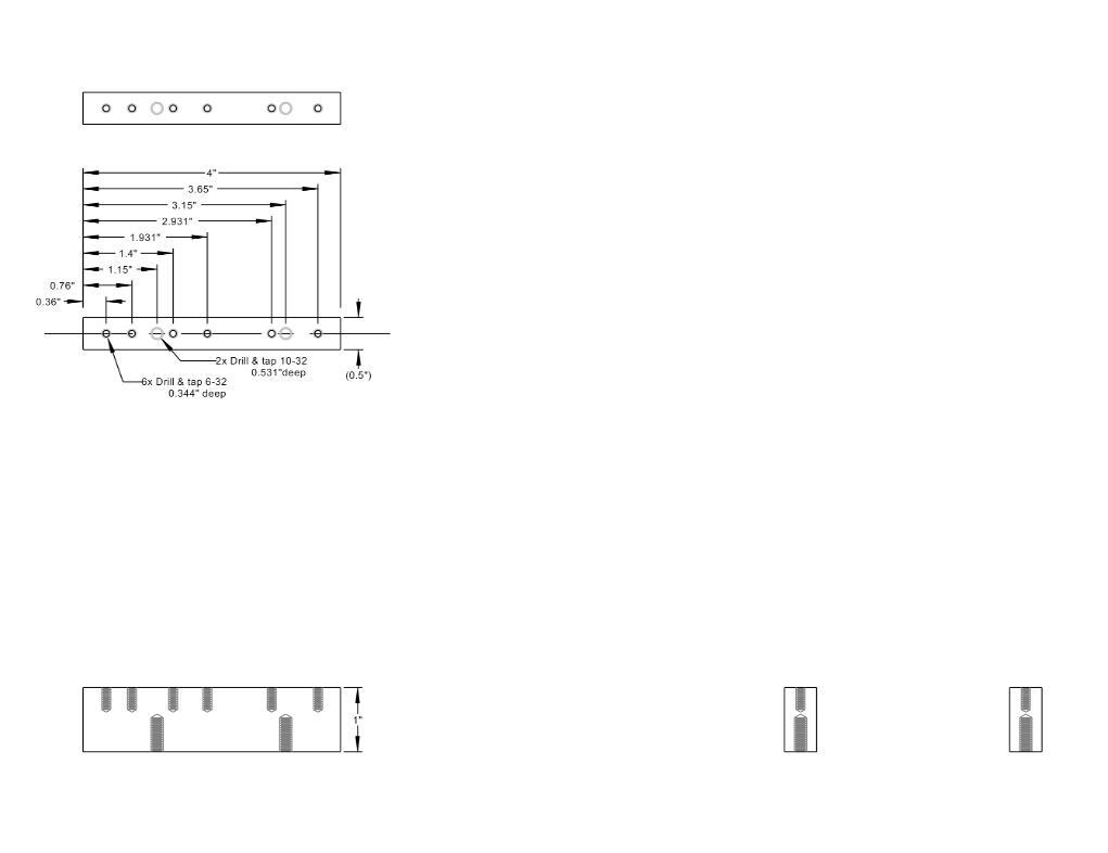
Install and start up the Brava DWG viewer, open the plans file you downloaded, and you will see all the layers of the plans. Select view, layer, and the Hide All button. Then click on only the layers you are interested in. For example BASE and BASE-DIM will yield the picture below. Change the background (View, Background Color, White) if needed.
Next: Take a close look at the mechanical assembly that we want to create:
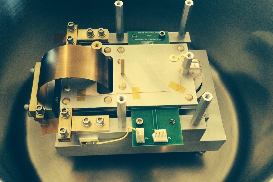
Some key features are shown above in this photo of an earlier version of the instrument
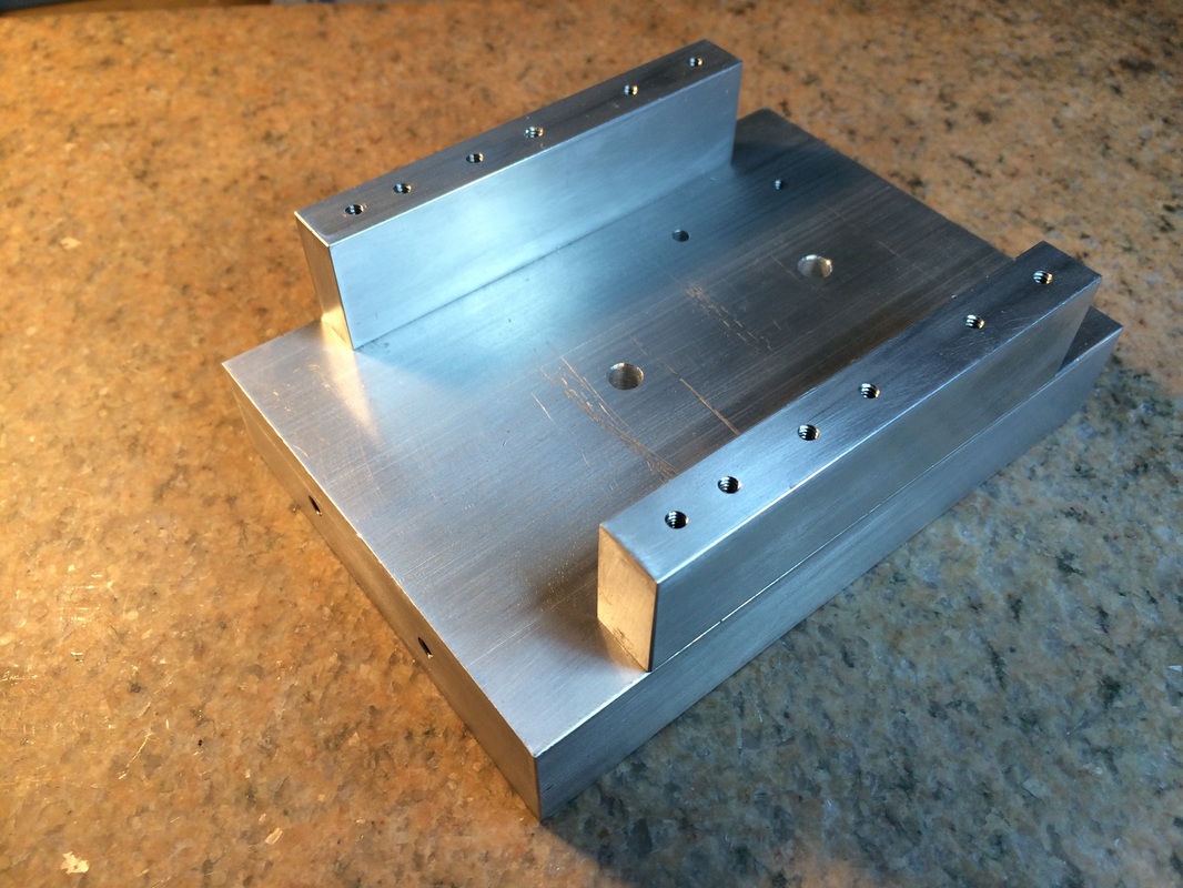
Building the Base
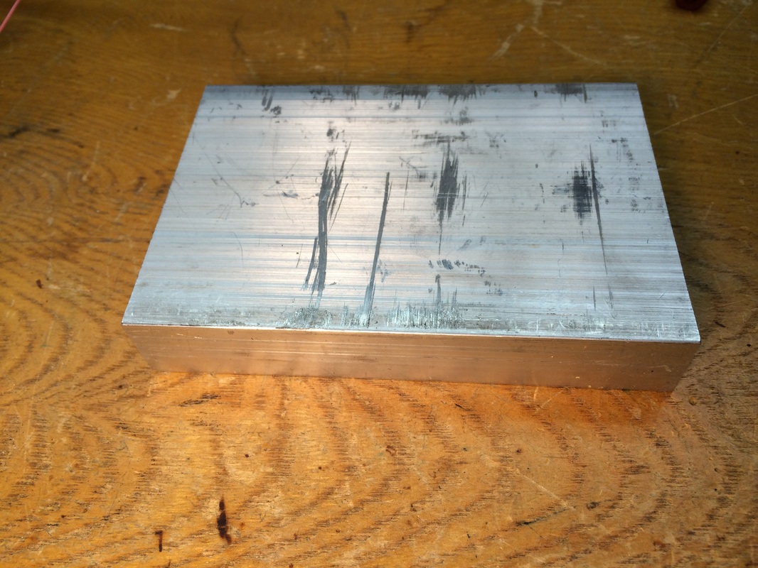
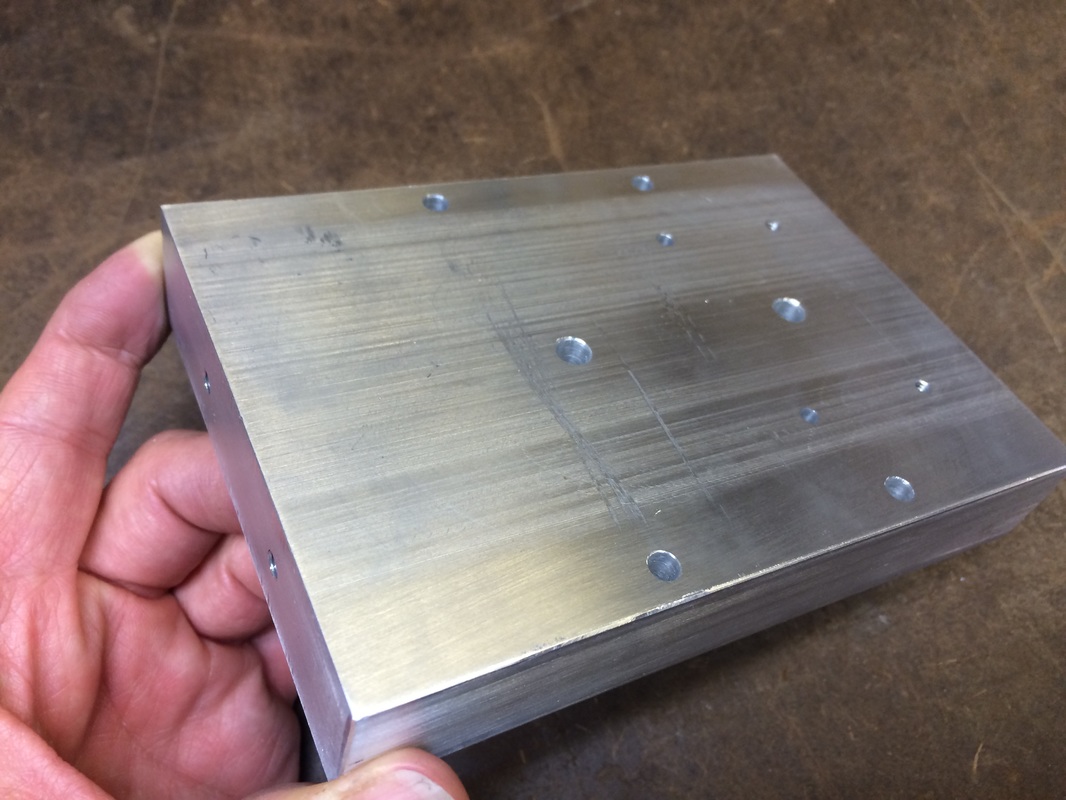
I started with a piece of aluminum from Online Metals. I had them cut the 1" x 4" material to 5.75" length, and they promise to make it that length or within 1/8" longer. My starting piece is shown here complete with ugly scratches on one surface (this was the most scratched of 3 pieces that I bought). I used a drill-mill to square up the ends and trim the length to 5.75". The length is not critical for the function of the instrument, so don't worry if your piece ends up slightly different in length. The raw material dimensions are fine for width and height as well.
I started with a piece of aluminum from Online Metals. I had them cut the 1" x 4" material to 5.75" length, and they promise to make it that length or within 1/8" longer. My starting piece is shown here complete with ugly scratches on one surface (this was the most scratched of 3 pieces that I bought). I used a drill-mill to square up the ends and trim the length to 5.75". The length is not critical for the function of the instrument, so don't worry if your piece ends up slightly different in length. The raw material dimensions are fine for width and height as well.
|
|
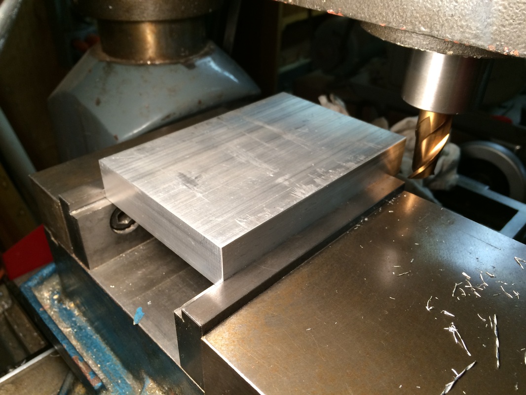
Next I located and drilled the holes in the bottom surface. I was especially careful to double check all dimensions prior to drilling. For improved accuracy I used a center drill to start each hole and then drilled slowly, clearing the chips frequently by retracting the drill. For the larger holes, I started with about a 1/2 sized drill, and then finished with the full sized drill. I drilled the holes in the order that they are indexed by letters in the drawing A through F. I used a real counter-bore on the holes marked C, but just used a 1/4" drill for the holes marked D. It is best to carefully set up a depth stop on your drill-mill or drill press for setting the depth of the blind holes and counter-bores
Take note that the three holes for the threaded feet are not drilled all the way through. This is important for the purpose of sealing the unit against atmospheric pressure variations with the floating case designed so as not to transfer pressure-induced case stresses back to the base. The case technique will be discussed in more detail later, but at this point just be sure that the 3 holes for the feet do not go all the way through the block.
After drilling, there are 7 holes to tap. For the 10-32 bottom tapped holes, I used a set of three taps that progressively move from regular tap to bottom-tap in shape. Always use Aluminum-compatible tapping fluid and proceed very carefully with your tapping operation breaking the chip frequently and removing the tap fully to clean the chips off. Take your time with the tapping feeling constantly for excessive resistance. You do NOT want to break a tap here.
For the two 6-32 tapped holes I recommend that you back drill from the bottom side with a 6-32 clearance drill to within 3/8 of an inch from the top surface. Then tap the 3/8 inch section that is left from the top surface taking extreme care not to overload the tap. If you don't know, the 6-32 tap size is about the easiest tap to break because they are small enough to be tender, and large enough to build up enough resistance to break them. Never tap dry, go slowly, break the chip every half to full turn by back-twisting 1/2 turn, and retract the tap if needed to clear the chips to avoid any significant resistance. If you are not very experienced tapping, practice first on parts you don't care about.
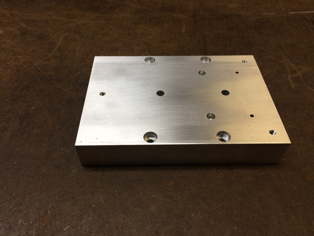
I finish the surface of the part by first reducing the scratches a bit by some light orbital sanding with about 100 grit paper just to hide the scratches. then I like to flatten and polish the surfaces of top and bottom by laying a piece of 400 grit wet-dry paper face up (sand sand side up) on a granite plate. Then I wet the paper with a little water and lap the part using straight strokes along the length on all surfaces. This is really not necessary, but it does serve to expose the flatness (or not) of the surfaces of the bar, and also make the final part very pretty as shown below. You can see in the picture of the top surface at the right that the lapping has made flat and parallel areas where the two side towers will be mounted. Again, this is probably not critical, but it is nice.
Deep scratches should be avoided around the 3 holes for the mounting feet so that the silicon rubber washers that will be placed there can make an air-tight seal with no leaks through any scratches.
Take note that the three holes for the threaded feet are not drilled all the way through. This is important for the purpose of sealing the unit against atmospheric pressure variations with the floating case designed so as not to transfer pressure-induced case stresses back to the base. The case technique will be discussed in more detail later, but at this point just be sure that the 3 holes for the feet do not go all the way through the block.
After drilling, there are 7 holes to tap. For the 10-32 bottom tapped holes, I used a set of three taps that progressively move from regular tap to bottom-tap in shape. Always use Aluminum-compatible tapping fluid and proceed very carefully with your tapping operation breaking the chip frequently and removing the tap fully to clean the chips off. Take your time with the tapping feeling constantly for excessive resistance. You do NOT want to break a tap here.
For the two 6-32 tapped holes I recommend that you back drill from the bottom side with a 6-32 clearance drill to within 3/8 of an inch from the top surface. Then tap the 3/8 inch section that is left from the top surface taking extreme care not to overload the tap. If you don't know, the 6-32 tap size is about the easiest tap to break because they are small enough to be tender, and large enough to build up enough resistance to break them. Never tap dry, go slowly, break the chip every half to full turn by back-twisting 1/2 turn, and retract the tap if needed to clear the chips to avoid any significant resistance. If you are not very experienced tapping, practice first on parts you don't care about.
I finish the surface of the part by first reducing the scratches a bit by some light orbital sanding with about 100 grit paper just to hide the scratches. then I like to flatten and polish the surfaces of top and bottom by laying a piece of 400 grit wet-dry paper face up (sand sand side up) on a granite plate. Then I wet the paper with a little water and lap the part using straight strokes along the length on all surfaces. This is really not necessary, but it does serve to expose the flatness (or not) of the surfaces of the bar, and also make the final part very pretty as shown below. You can see in the picture of the top surface at the right that the lapping has made flat and parallel areas where the two side towers will be mounted. Again, this is probably not critical, but it is nice.
Deep scratches should be avoided around the 3 holes for the mounting feet so that the silicon rubber washers that will be placed there can make an air-tight seal with no leaks through any scratches.
Bottom view of base
|
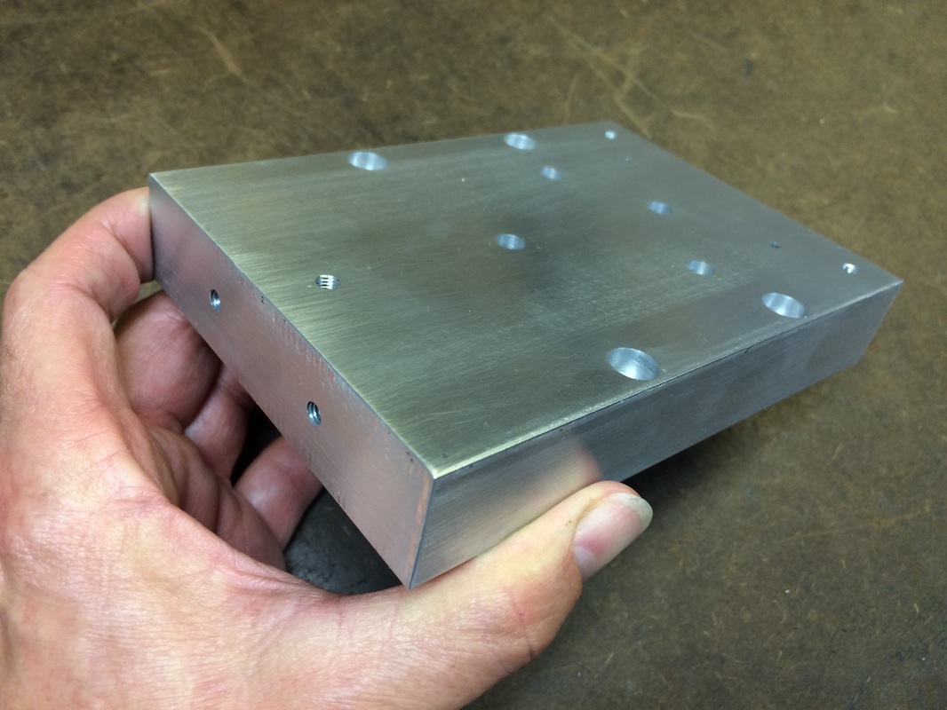
Shows holes on bottom and end
|
Top of finished base
|
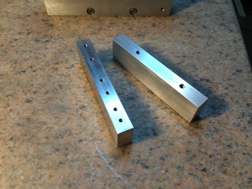
Side towers
Next we make the side towers. The drawing can be extracted from the plans by turning on only the layers for TOWERS-2 and TOWERS-2-DIM:
Next we make the side towers. The drawing can be extracted from the plans by turning on only the layers for TOWERS-2 and TOWERS-2-DIM:
Again the metal material can be found at Online Metals. Here is the link.
The raw material is .5" x 1" and cut to 4+ inches long.
|
Use a milling machine or alternatively a hacksaw and sander to trim the length of the bars to 4". The length is not really critical, just measure all the hole locations from the left end of the part as indicated on the drawing. I suggest that you lay out and center punch the holes carefully, and then use a center drill followed by the specified drill size for the holes to be tapped. I drill all the holes on the top, then on the bottom, and then I go back and tap all of them carefully. I like to finish the parts by sanding on the granite block, but an easy alternative is to use the orbital sander approach to beautify the surface.
I recommend that all the holes be drilled 3/4" deep to make it easier to tap them. You could even drill all the way through to make tapping easier. There is no functinal reason for the blind holes. Be sure to go slow with the tapping, and keep the chips cleared out. Again, the 6-32 tap is easy to break. Always use tap fluid, and back up to break chip and clear the chips if you ever feel much resistance. I like to clean the parts up with rubbing alcohol. I get 91% Isopropyl Alcohol at the drug store. It is cheap and it's safer than most solvents so I use it to clean everything. Now we have three parts made. So we can attach them together with four 10-32 x 1-1/4" socket cap screws. Next up is the brass part at the end of the base that holds the spring clamp. We call it Tower 1 and it is made out of 1/4" thick brass plate that is 2" wide. You can get the raw material at online metals as before: here 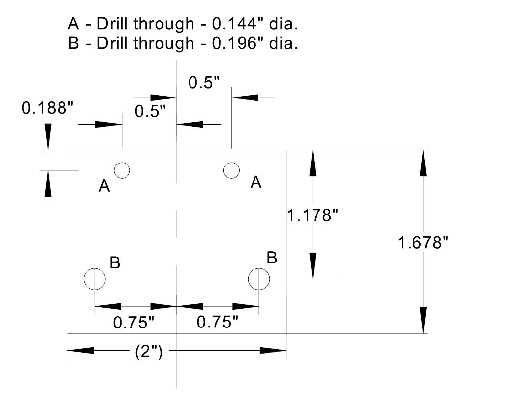
|

|